The circuit illustrated here is used as Burglar alarm. PIR Sensor is the heart of this simple burglar alarm circuit using arduino.
Burglar Alarm Project With Circuit Diagram
12072020 Exit Delay For Burglar Alarm Circuit.

Burglar alarm circuit construction. LDR is kept at such a place that when thief enters our house then a shadow will fall on the LDR. 26072012 Burglar alarm Circuit using IC 555. This circuit is based on a sound detection through an inexpensive piezo element.
This work present the design construction and testing of a simple burglar alarm activated by light break beam and pressure sensor. PIR sensor used to detect body motion and UM3561. 12122015 Burglar Alarm Circuit.
They help alert security personnel especially in situations where no obvious break-in has occurred. This biases Q1 on through resistors R2 and R3. It connects to the source of power the trigger section which produces trigger current touch section that controls the supply of power in the circuit alarm section that sounds when current.
The R1 stand gives to get the maximum score. The testing followed the modular pattern used in the design with each functional block being tested. If an intruder tries to break in the door would be disturbed instantly activating the connected piezo sensor and the preceding alarm circuit.
It connects to the source of power the trigger section which produces trigger current touch section that controls the supply of power in the circuit alarm section that sounds when current. You may assemble the circuit as shown in the diagram. Aluminum foil speaker battery Figure 1.
When you close the ONOff switch the burglar alarm starts working with a time dalay given by the C5 capacitor. The entire system may be fixed over the door or the restricted entrance. All these will bring alarm the way by which criminal break into private properties by scaring them away once the alarm is trigger on.
The home alarm circuit is designed to build up a circuit that goes through the paper house as shown in the figure 1. C1 could be greater or lowered in value to change the delay periods. The circuit is very easy to construct and the cost less.
The type of alarm system been built is called INTRUDER ALARM SYSTEM and it is simple but effective alarm circuit which can reset itself after a time that which have been selected. When the ray of light falls on the light sensor the alarm is triggered and the siren begins to operate the speaker beeps and the flasher light flashes. The design was simulated on electronics work bench 11.
Sound activated burglar alarm circuit Construction and Testing The sound activated burglar alarm circuit was constructed in accordance with the circuit designed as illustrated Figure 4. Visual display of the burglar alarm circuit. The power supply section.
A small beam of light source is also needed to supply continuous signal to LDR. DESIGN AND CONSTRUCTION OF BURGLAR ALARM CIRCUIT WITH DISPLAY UNIT ABSTRACT Burglar alarm circuit is made up of five major sections. Speaker to produce Police siren.
Construction and Testing. This PIR burglar alarm circuit provides sound alert against unauthorized entry or movements. The principle of operation of this burglar alarm is simple.
Before getting into working of the alarm circuit I shall brief the components used in this project. Many security alarms were designed and published in Electronics hub. The design was simulated on electronics work bench 401 Q 78 Ac source 4060B LM 386 MICROPHONE 50K 1UF 50V 10UF 16V 10K 100UF 16V 1000UF 16V 0022UF.
04092020 Intruder Alarm Using a Piezo Electric Sound Sensor. Zener diode 51V Resistor 560Ω100KΩ 10KΩ. Switching on S1 charges C1 to the supply voltage.
Burglar alarm system is an important part of home security systems. At this period the economy not good Make have steal plentiful. This burglar alarm project is based on PIR sensor UM3561 and Speaker.
The Alarm Sound Super Bell loud forever until will cut power supply to go out. When the Switch of the magnet Senate was opened or strip metal torn. The circuit diagram to build a simple burglar alarm or an intruder alarm using arduino is given below.
Burglar alarm systems can be used in residential buildings commercial buildings offices industries and even in military locations. Motion sensors are an important part of most burglar alarm systems. Sound activated burglar alarm circuit.
When the ONOFF switch is open the device does not work. It is becoming more and more popular among the homeowners because of the consistency with which it performs. Burglar alarm circuit or Theft alarm circuits are quite common and different circuits uses different methods to detect intruders.
A burglar alarm system is designed to detect an unauthorized entry into a house or area. For best Light source we can use Laser diode which will work for few km. Today there are different types of home security systems available in the market and they perform in different ways to detect potential intrusions.
The power supply section. A voltage is obtainable with the time frame from the delay interval to keep the alarm circuit switched off. The above circuit uses timer IC 555 to detect and sound alarm upon detecting intruders.
We come to try build the circuit steal model to is simple better. The burglar alarm is one of the most reliable means to secure a house or a work place. 08082017 Simple burglar alarm circuits.
Just for fun I created a burglar alarm circuit using NE555 and. Many types of motion sensors can sense motion in total darkness without an intruder becoming aware that an alarm has been triggered. Speaker is connected to any terminal of the battery and one side of.
555 Based Alarm Circuit. Design and construction of burglar alarm circuit with display unit ABSTRACT Burglar alarm circuit is made up of five major sections. The sound activated burglar alarm circuit was constructed in accordance with the circuit designed as illustrated Figure 4.
Two door sensors can be connected to the circuit in NO or NC configuration. It has normally closed and normally open triggers which make this door as a.
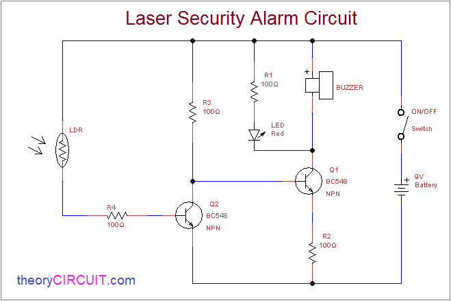
Laser Security Alarm Circuit

Remote Controlled Alarm Circuit

Wiring Material Motorcycle Alarm With Transistor Circuit Diagram Transistors Alarm Circuit Diagram

Anti Theft Car Alarm Circuit

How To Make A Burglar Alarm Circuit For Your Home Security Home Security Systems Wireless Home Security Systems Burglar Alarm

Sound Activated Burglar Alarm Circuit Download Scientific Diagram

Pin On Electronics

Simple Scr Security Alarm Circuit Diagram Image Circuit Diagram Circuit Electronics Basics
An Scr Based Burglar Alarm Circuit Diagram


0 comments:
Post a Comment