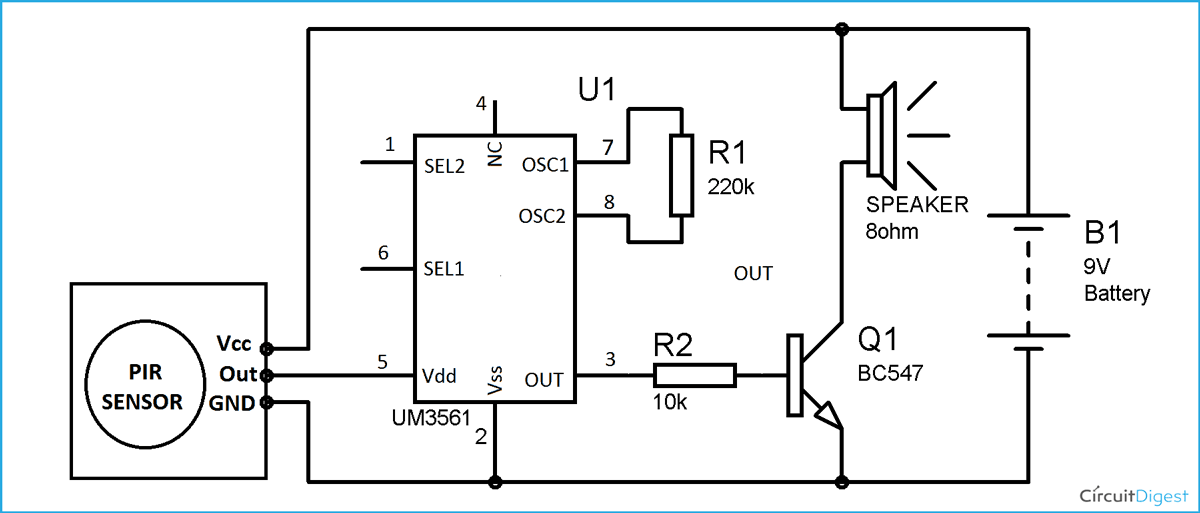
PIR sensor used to detect body motion and UM3561. Speaker to produce Police.

Low Cost Burglar Alarm For Boats Circuit Diagram
Burglar alarm system is an important part of home security systems.
Burglar alarm experiment. This circuit detects an unauthorized entry of any person in the houses or in any particular area. LDR is kept at such a place that when thief enters our house then a shadow will fall on the LDR. At Projects for School we have designed a very simple and thorough kit that will enable you to demonstrate how a Burglars alarm functionsIn fact now you can Build Your Own Model of burglars alarm.
So Now you know how an IR sensor works. This circuit convenients for to set up in an automobile. Here I will be bending the legs of the LED and photodiode so that they are facing each other.
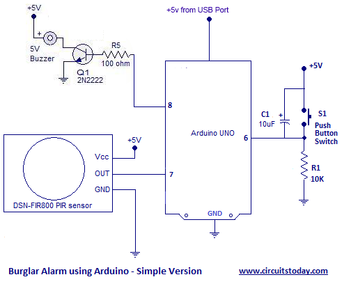
Thus we have designed a home security alarm system using Arduino and PIR motion sensor which is handy portable cost-effective and highly effective as well. Place the detector pad under a mat where you want to catch someone and simply wait for them to come along and stand on the mat and they will be caught. But in case of car owner opens in and out while note as a result have no result anything because of the transistor model PNP to still dont work.
As the IR receiver is connected in reverse bias condition when the rays fall on it it conducts a current. The alarm makes use of different types of sensory elements like motion sensor or laser security alarm for intrusion detection. Is a simple project that can be used for STEM and provide an afternoon of fun building it and then many more hours catching the family out.
You wont need more than 1 minute to set this up. These infrared rays fall on the surface of the IR receiver. This is how we set up the entire circuit.
So this project is all about building an anti theft alarm or an intruder alarm using Arduino and PIR sensor. 15092016 Description Burglar alarm is a very simple interesting and a fun project for a Science Activity Workshop or even for submission as a Physics Project for Class 11 th and 12 th. 27052020 In this burglar security alarm LM358 op-amp IC is configured as a comparator in this project.
08082017 Car Burglar Alarm timer alarm system circuit model to economize. 08012020 In this tutorial we are going to design a burglar alarm circuit. It is possible to enhance this project with many features like adding a GSM module to send SMS alerts to specified mobile numbers when an intruder is detected when a.
12122015 Burglar Alarm Circuit. The project uses a PIR motion sensor instead of a Transmitter and a receiver. A Burglar Alarm is basically an intruder alarm or an anti theft alarm.
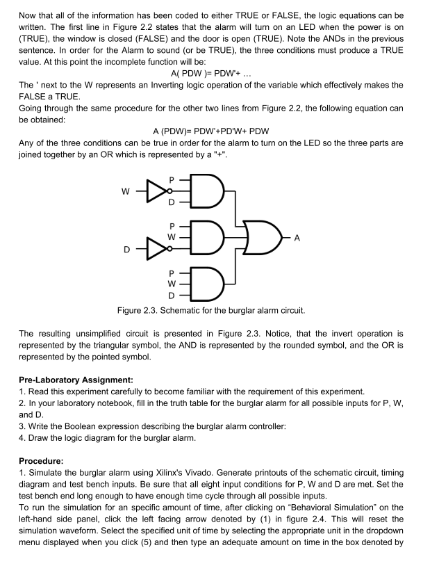
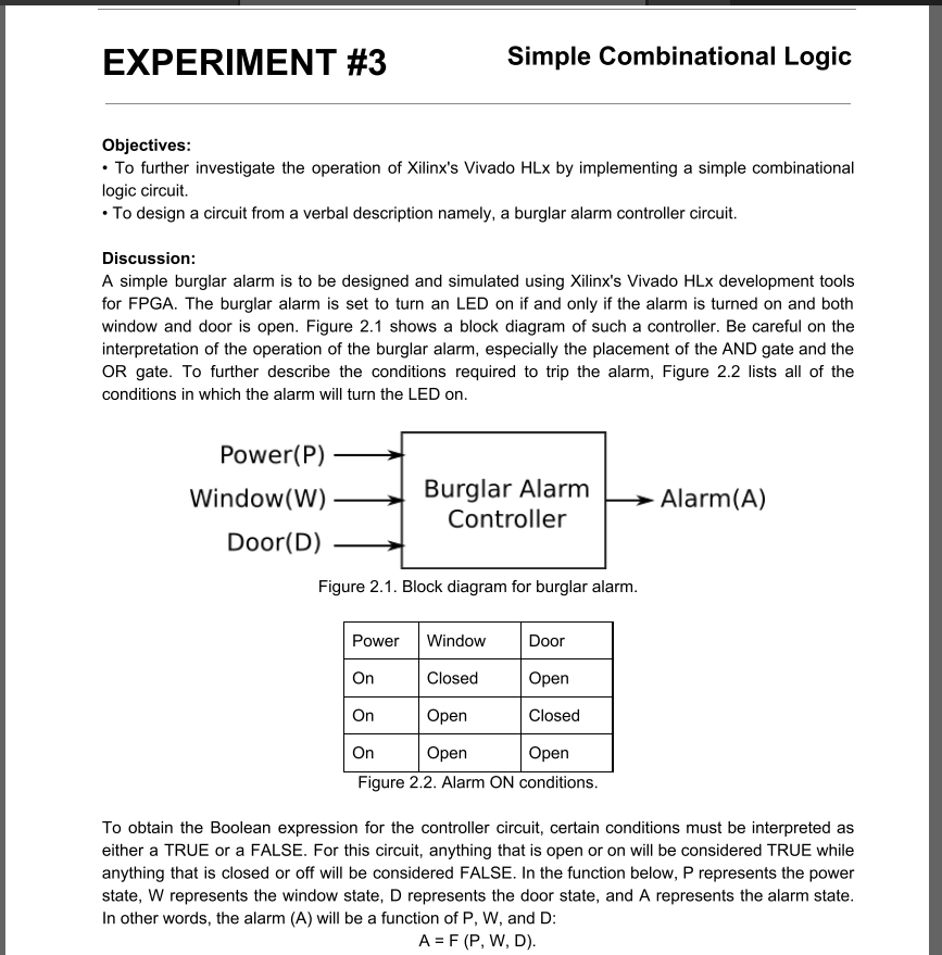
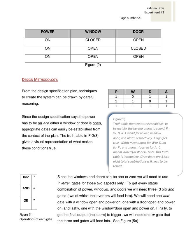
Figure 21 shows a block diagram of such a controller. We will start building our Burglar alarm. Burglar alarms or alert systems can be designed in different ways.
A 9V battery the correct scientific term is a cell A 9V battery cell holder. A simple burglar alarm is to be designed and simulated using Xilinxs Vivado HLX development tools for FPGA. 27042020 An intrusion detection alarm or burglar alarm is an alarm circuit which is consisting of some electronics components.
First we need to choose the sensor I selected Hall effect sensor because its very simple and easy to use its working based on the proximity of magnet so we can measure the magnetic field based on the output voltage and if we can put the sensor. Such alarm systems are hugely in demand for security purposes and thus the given system can be proved useful and effective in view of the above features. A Simple Circuit Hands-On Experiment Bayram Akarsu bakarsuerciyesedutr Science Education School of Education Erciyes University Kayseri Turkey Abstract Hands-on activities are one of the most popular instructional tools that enhance student understandings of the.
A wooden clothes peg. Usually switch at set up keep with automobile door will the circuit closes. This burglar alarm project is based on PIR sensor UM3561 and Speaker.
Used to detect any human activity or entry gate security violations. This project is very simple. The circuit illustrated here is used as Burglar alarm.
Apart from being one of those fun science projects the aim is to make a simple burglar alarm using electronics and a clothes peg as a switch. Attach both wires of the one end of the flexi-wire to the battery holder by joining the wires together and then wrapping insulation tape around the joins. Strip about 1cm of the plastic insulation off the one end of both wires of the flexi-wire using the sharp knife.
The burglar alarm is set to turn an LED on if and only if the alarm is turned on and both window and door is open. When the whole system is turned on the IR transmitter starts to emit infrared rays. From very simple sound alarm system to the advanced and feature rich system which will send SMS alerts activate sound alarm turn ON lights turn ON CCTV cameras close the main gate etc.
A burglar alarm is basically an intruder alert system used to prevent theftrobbery and protect ones premises. For best Light source we can use Laser diode which will work for few km. Approximately a meter of flexi-wire.
We are going to build a burglar alarm for that we need to use sensor that sense presence or something as input device and we also need output device as a alarm the people here we are using buzzer. A small beam of light source is also needed to supply continuous signal to LDR. It is a simple and cost-effective solution for the security system.

9 Burglar Alarm Circuit Ideas Electronics Projects Circuits In 2021 Electronics Projects Burglar Alarm Burglar

Burglar Alarm Soldering Kit Robotshop
Burglar Alarm Circuit And Projects Diy
Practical Gated Burglar Alarm Circuit Diagram Under Alarm Circuits 59867 Next Gr

Experiment 3 Simple Combinational Logic Objectives Chegg Com
Experiment 3 Simple Combinational Logic Objectives Chegg Com

Amazon Com Small World Toys Science Room Alarm Lab Experiment Kit Toys Games
Lab 2 Simple Combinational Logic
Burglar Alarm Project With Circuit Diagram


0 comments:
Post a Comment