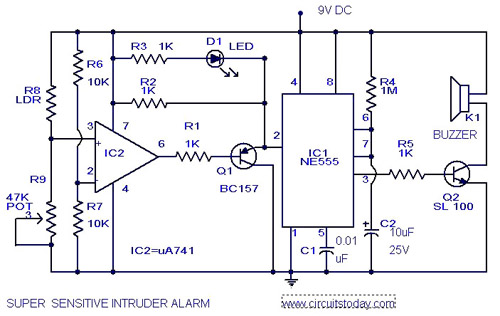
Picture of our Burglar Alarm project This circuit uses a popular timer IC which is 555. 27052020 Working Principle of Burglar Security Alarm In this burglar security alarm LM358 op-amp IC is configured as a comparator in this project.
Alarm Circuit Page 14 Security Circuits Next Gr
Once found the system sends emergency signals to the user or.

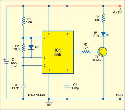
Burglar alarm circuit working principle. On detecting day time it auto-shuts down and then the battery starts charging via DC adaptor. 15022016 Circuit Design of Burglar Alarm System The IR transmitter or IR LED is connected to a current limiting resistor of 150Ω and connected to supply. In a ddition burglar alarm is able to make phone calls and text messages to inform the user.
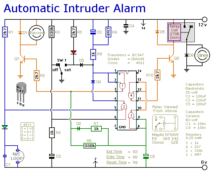
08082017 Burglar Alarm model the circuit closes This circuit works with battery 9V a piece is very small. Lets see how they work. Via sensors and contacts they detect movement or the opening of doors and windows upon which a loud alarm is produced to alert those nearby of the unauthorised entry.
WORKING OF THE CIRCUITRY. In any circuit whether its powering a flashlight or a computer electricity only flows when you give it a path between two points of opposite charge. The operation of a burglar alarm is the same that of an electric circuit.
We can find many name for the burglar alarm and the most basic definition of security system is found in its name. IC 555 is connected as comparator with pin 6 connected with positive supply the output goes high-1 when the trigger pin 2 is at lower than 13 level of the supply voltage conversely the output goes low-0 when it is above 13. To turn the electricity on or off you open or close part of the circuit.
13052016 In the First semester along with Pranav I tried to design a burglar alarm circuit that would go off if the burglar tripped over a copper wire. Other than the family dog the most basic burglar alarm is a simple electric circuit built into an entry way. These infrared rays fall on the surface of the IR receiver.
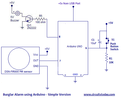
02122020 Working Principle of PIR Sensor Burglar Alarm System When the PIR Sensor detects any human body movement its OUTPUT pin becomes HIGH Vcc and when it does not detect any human body movement its OUTPUT pin becomes LOW Ground. For the work happens independently dont be under house electricity. The control unit of the system is connected with the sensors through either narrowband RF signal or low-voltage hardwire and these in turn are joined to a means which announces the alarm to extract response.
The project uses a PIR motion sensor instead of a Transmitter and. So UM3561 activated and start producing sound with Speaker. The circuit will make a noise to warn work as soon as detect which be switch model usual close the circuit or aluminum eliminated separate.
05042017 A burglar alarm system consists of a series of electrical components that are connected to a property. This circuit detects an unauthorized entry of any person in the houses or in any particular area. Burglar alarm working principle.
12122015 This burglar alarm circuit is very simple whenever PIR sensor detects any human body movement its OUTPUT pin becomes HIGH which is connected to UM3561s Power supply PIN 5. After that starts serving its motion detection and human detection work. Basically the burglar alarm is a device that monitors the designated area or areas to detect the presence of suspicious elements.
The design looks very simple since most of the complex infrared detection is carried out by the advanced PIR module itself. All you need is just to place this circuit in front of the locker or below the mat so when any unknown person come and walk over the switch the circuit will trigger and sound of alarm comes. For example one has to turn on a switch to turn of the lights or any other appliance.
This circuit will help you to guard your precious documents as well as jewellery from intruders or theft. 27042020 The circuit is a loud sound alarm burglar alarm with enhanced functionality that it automatically turns ON on detecting dark. It is a simple and cost-effective solution for the security system.
Now-a-days you would find that most of the Burglar alarms are available in electronic form. It is placed at the maximum possible range from photo diode. 08012020 Burglar Alarm Circuit Electronics Projects.
In order to know about burglar alarms and how they work one has to compare them to a simple electric circuit or appliance. By adopting physical method or electronic technology the automatic detection occurs in the protection monitoring area inside the intrusion behavior by this way which produces the alarm signal. We built a small scale working model of the circuit and presented it in one of the How Things Work Session which is organised by the Robotics Club in association with the Electronics Club of IIT Bombay.
This principle works in the same way with burglar alarms. In this tutorial we are going to design a burglar alarm circuit. 03032020 The operating principle of the proposed burglar alarm circuit can be understood by referring to the following block diagram.
The system takes the help of the sensor to detect such elements. The PIR module converts the IR radiation from human body into corresponding electrical signal. The cathode of the photo diode is connected to supply while anode is connected to 10KΩ resistor.
When the whole system is turned on the IR transmitter starts to emit infrared rays. How does a Burglar Alarm work. 13022014 Burglar alarms are networks of integrated electronic devices working together with a central control panel Brain to protect against thefts and other possible illegal entries as well home intruders.
Infrared Burglar Alarm Detailed Circuit Diagram Available
Alarm Circuit Page 7 Security Circuits Next Gr
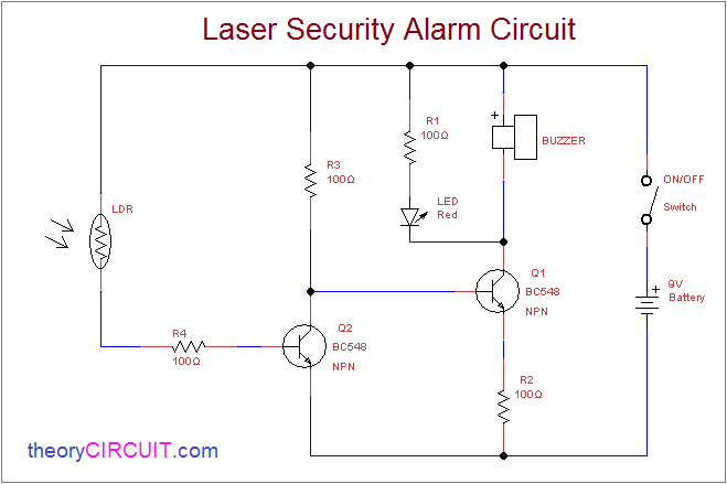
Laser Security Alarm Circuit
Burglar Alarm Circuit And Projects Diy
Long Range Cordless Burglar Alarm Circuit And Its Working

Alarm Circuit Page 10 Security Circuits Next Gr
Simple Security Alarm Circuit Working And Applications

Sound Activated Burglar Alarm Circuit Download Scientific Diagram
Burglar Alarm Project With Circuit Diagram


0 comments:
Post a Comment