The most common burglar alarm sensors for doors are hardwired magnetic switches also known as contacts. This alarm will be activated if an unauthorized person is detected by a Window Sensor or a Motion Detector.
Dnt 253 Programmable Logic Controller Converting Relay Schematics
This alarm will be activated if an unauthorized person is detected by a Window Sensor or a Motion Detector.

Burglar alarm ladder diagram. This is PLC Program for Alarm Security System. Basic elements of a relay diagram. If windowdoor sensor is broken turns off sound alarm and turn on lights.
A R1 PB1 PB2 R1 R1 start emergency stop Rail Rung 22 23. 13012003 I am to layout a ladder diagram for an alarm panel for our plant. Alarm should be ON when any person will be detected by the motion sensor.
Alarm Security System This is PLC Program for Alarm Security System. Line A is from the secret control switch line B is from a pressure sensor under a steel safe in a locked closet line C is from a battery-powered clock and line D is connected to a switch on the locked closet door. Diy auto burglary alarm circuit diagram electronic schematics and circuits collection for student.
Implement this Alarm System in PLC using Ladder Diagram programming language. LL984 inside Concept provides the same tools as Modsoft 984 ladder logic. Through the use of ladder logic logic statements and functional block diagram programmi ng techniques.
LADDER DIAGRAM The left vertical line of a ladder logic diagram represents the power or energized conductor. When possible every opening should be home-run meaning each has its own individual wire running to the main panel. 17072018 PLC Program for Alarm Security System.
If only one of the inputs sensors is turned on nothing will happen. Perimeter contacts use 2-conductor burglar alarm wiring run from each opening to the main alarm panel. It has provision for both normally-closed and normally-open contacts and a 24-hour Personal AttackTamper zone.
I nid it urgently for my poly project. Problem Description A feeder drops material on the conveyor which sends material for further process through one more conveyor. Concept operates with either.
Logical combination of these conditions determines when and in what way instruction on the right will execute. The LabVIEW software is used for both the design and simulation of fire alarm. Line on the left is called a bus bar and lines that branch off to the right are instruction lines.
The devices are wired to the following locations. 26042009 Ladder diagram consists of one vertical line found on the left hand side and lines which branch off to the right. Problem Description Make burglar alarm system program in S7-1200 PLC.
16052017 LADDER DIAGRAM A ladder diagram also called contact symbology is a means of graphically representing the logic required in a relay logic system. If two of the inputs are turned on the Red Pilot Light will be activated. 03052006 plc ladder diagram help.
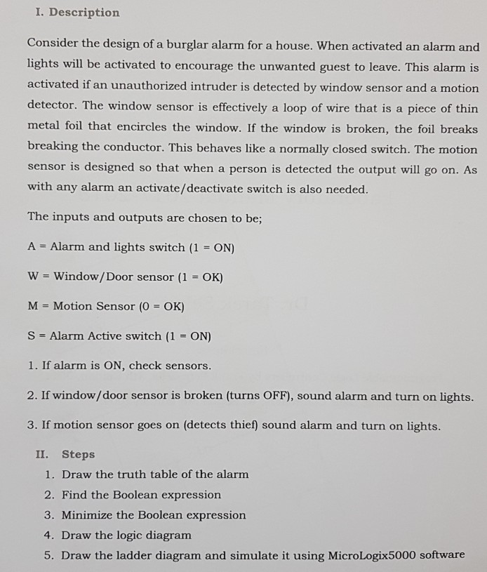
04082010 August 4 2010. Consider the design of a Burglar Alarm for a house. If three of the inputs is turned on at same time it would trigger an Alarm SIREN 4.
The students use a variety of software in the course that includes cir cuit software and LabVIEW. 13012021 A burglar alarm is designed so that it senses four input signal lines. Problem Description RUNG000 simply shows a latching of a.
Note in Figure 6 that the alarm sensors are arranged in blocks or groups each of which is allocated a specific zone input connection point on the main control unit. S Bharadwaj Reddy July 17 2018 March 5 2021. Ladder Diagram ladder logic complies with the IEC 1131-3 ladder diagram specification.
20072021 A schematic or schematic diagram is a representation of the elements of a system using abstract graphic symbols rather than realistic pictures. It will involve one central located panel which will be able to monitor nine different fault possibilities throughout the plant ie. The schematic diagram software is compatible with ms programs.
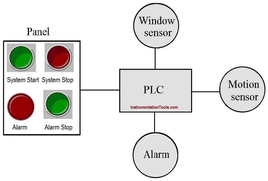
By using the Expansion Modules you can. Block diagram of a basic burglar alarm system. Consider one house in this we want to arrange automatic burglar alarm security system.
Problem 172 Draw a ladder diagram that will cause output D to go true when switch A and switch B are closed or when switch C is closed. Consider one house in this we want to arrange automatic burglar alarm security system. Do any of u guys have a plc ladder diagram of a estate burlgar alarm system.
More A One-Time-Only Burglar Alarm. Conditions which lead to instructions positioned at the right edge of a diagram are stored along instruction lines. Low boiler water low cooling sump levels power failure etc.
01052021 Sometime engineer can get data from Fire Alarm Panel as integration. MS Windows 31x Windows 95 or Windows NT. Alarm should be ON when any person will be detected by the motion sensor.
Make burglar alarm system program in S7-1200 PLC for the house. This circuit features automatic Exit and Entry delays and a timed Bell Cut-off. Implement this Alarm System in PLC using Ladder Diagram programming language.
If alarm is on check sensors. Consider the example of a burglar alarm. The burglar alarm systems block diagram thus takes the basic form shown in Figure 6.
Make burglar alarm system program in S7-1200 PLC for the house.

Plc Program For Alarm Security System Plc Tutorials And Programming
I Description Consider The Design Of A Burglar Al Chegg Com

2019 2023 Redundancy Detection System Market Comprehensive Study Explores Huge Growth In Perimeter Security Wireless Security System Home Security Systems

Fire Alarm System Wiring Diagram 10 Addressable Car Harness New Fire Alarm System Fire Alarm Alarm System
1
Plc Program For Alarm Security System Plc Tutorials And Programming
Ebook Engineering Analysis Using Scilab And C

Plc Program For Alarm Security System Plc Tutorials And Programming

Ladder Logic Diagram For An Alarm System As Shown In Figure 1 Download Scientific Diagram


0 comments:
Post a Comment