Burglar Alarm Circuit Diagram is available on PDF ePUB and DOC. S1 and S2 are the two switches that are used in the circuit so that both can be put in two different places ie.
Alarm Circuit Page 17 Security Circuits Next Gr
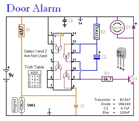
The schematic for the door alarm circuit is shown below.

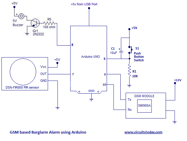
Burglar alarm circuit using scr pdf. The 9 volts that are supplied to this circuit are in parallel with the 10KΩ resistor and the knife switch with the gate of the SCR being connected to the middle. As shown in the circuit diagram the sensor is an ordinary thin wire conductor which is laid across the restricted area in such a way that anybody intruding the place gets caught up against the conductor and in the course breaks it up. PIR sensor used here to detect body motion and UM3561.
Thus we have designed a home security alarm system using Arduino and PIR motion sensor which is handy portable cost-effective and highly effective as well. One of them can put in front of the locker while another one can be placed on the front door. 18032008 So lets build a burglar alarm using transistor and scr as main components.
They are also called ThyristorsI used TIC106Ds because they are widely availableBut - provided the current voltage and power ratings are adequate - practically any type of SCR will work fine. The circuit will emit a warning sound from a loudspeaker hear immediately. When we forget to shut the door.
Burglar Alarm Project Burglar Alarm Circuit Using Scr. 12122015 Burglar alarm system is an important part of home security systems. OF SIMPLE BURGLAR ALARM CIRCUITS USING SINGLE TRANSISTORLASER BEAM ALARM CIRCUIT DIAGRAM WORDPRESS COM APRIL 15TH 2018 - BURGLAR ALARM CIRCUIT OR THEFT ALARM CIRCUITS ARE AVAILABLE.
SCR Based Burglar Alarm. Speaker is connected to any terminal of the battery and one side of. This circuit uses two SCRs - or Silicon Controlled Rectifiers.
Its features include automatic Exit and Entry delays - together with a timed Bell cut-off and Reset. An SCR Based Burglar Alarm. This is a simple SCR based burglar alarm circuit.
08082017 Forget door alarm circuit. Shows simple burglar alarm circuit which makes enclosure or on the door for the purpose of protection against burglary scr is connected in the circuit as shown in fig. This is probably the simplest one among all.
Scr Current Limiting Circuit Breaker Burglar Alarm continuous duty rated c w o p voltage and current working with the trip characteristic curves of abb sace current limiting circuit in projects for engineering gt circuits gt an scr based burglar alarm l54773 next gr ge distribution tec36003 spectra series adjustable variable speed scr dc motor. With minimal components used to design the system this project is a cheaplow cost burglar alarm circuit. We will use a knife switch in conjunction with a 10KΩ resistor- the 2 of these components form a voltage divider circuit.
This intruder alarm or burglar alarm circuit is based on PIR sensor UM3561 and Speaker. Visual display of the burglar alarm circuit. Its designed to be used with the usual types of normally-closed input devices such as - magnetic-reed contacts - micro switches - foil tape - and PIRs.
Its features include automatic Exit and Entry delays - together with a timed Bell cut-off and Reset. Description Here is a simple but effective burglar alarm circuit that can be. Limiting resistor R and the micro switch are connected at the gate of the scr.
By using a switch stick at the door. Picture of our Burglar Alarm project This circuit uses a popular timer IC which is 555. This is a door alarm circuit uses to warn.
With the SCR switched ON a route to ground is supplied by means of BZ1 a 6- to 12 -volt bell and SCR1 resulting in BZ1 to sound the alarm. When the switch S1 is pressed diode D1 which is linked with it starts conducting as the transistor T1. Such alarm systems are hugely in demand for security purposes and thus the given system can be proved useful and effective in view of the above features.
04012021 The burglar alarm circuit is attached to the SCR anode and gate. This simple burglar alarm circuit is designed using transistor BC107 and SCR TYN612. Of course - the pin configuration may be different from.
This is a simple SCR based burglar alarm circuit. The home alarm circuit is designed to build up a circuit that goes through the paper house as shown in the figure 1. IC 555 is connected as comparator with pin 6 connected with positive supply the output goes high-1 when the trigger pin 2 is at lower than 13 level of the supply voltage conversely the output goes low-0 when it is above 13.
The micro door switch remains in the OFF position when the door is closed. Alarm Circuit Diagrams Circuit. The circuit working When stick switches S1 at the door which in usual time switch still pressed.
28022013 Intruder Alarm Using an Ordinary Conductor as the Sensor. Circuit breaker molded case circuit breakers siemens gt circuits gt an scr based burglar alarm l54773 next gr scr burglar alarm testing your circuit zen internet us5233330a alarm circuits to indicate the open status of scr technology lamarchemfg com scr protection circuits electronic circuits and diagrams continuous duty rated c w o p. Micro-power over temperature alarm PDF Miniature loop alarm Miniature Loop Alarm Modular Burglar Alarm.
An SCR Design with a 10 Amp rating Car battery voltage tester using LM3914 Car burglar alarm circuit Car Door Keypad Using LIN network Car Nicad charger Car OBD II J1850 PWM J1850 VPW ISO-9141 cables. Any type of slight pressure on the mat switches ON the contacts of the mat switch that switches ON current to the SCR gate triggering it to. 04092015 Working of Security Alarm Circuit.
Aluminum foil speaker battery Figure 1. We do not shut the door switch. An SCR Based Burglar Alarm - Circuit Diagram.
Speaker to produce Police. Its designed to be used with the usual types of normally-closed input devices such as - magnetic-reed contacts.

Door Open Alarm Circuit Using Reed Switch Circuit Electronic Circuit Projects Switch
3

Sensitive Fire Alarm Circuit Using Infrared Ir Led Fire Alarm Alarm Electronic Circuit Projects
An Scr Based Burglar Alarm Circuit Diagram

Burglar Alarm Circuit And Projects Diy

Pin On Electronics
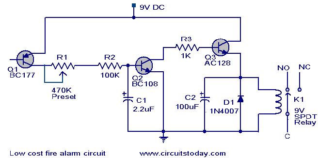
Low Cost Fire Alarm Circuit Working Circuit Scematic

Alarma Por Ruptura Laser Teoria Practica Aplicacion Tecnica Del Scr Youtube Security Alarm Wireless Home Security Systems Home Security Systems

View Transistor Based Security Alarm Pictures Sipeti


0 comments:
Post a Comment