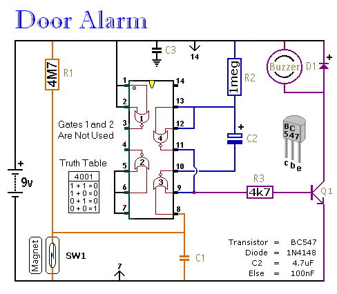
When the Switch of the magnet Senate was opened or strip metal torn. 08082017 Simple burglar alarm circuits.
Alarm Circuit Page 17 Security Circuits Next Gr
The first one is a simple burglar alarm circuit using pir sensor arduino a buzzer and a push button switch.
Burglar alarm circuit project pdf. Visual display of the burglar alarm circuit. This burglar alarm system circuit is using a infrared proximity detector that triggers an alarm when the rays falling on its sensor are interrupted. Acces PDF Burglar Alarm Project With Circuit Diagram Burglar Alarm Project With Circuit Diagram Thank you certainly much for downloading burglar alarm project with circuit diagramMost likely you have knowledge that people have look numerous times for their favorite books in imitation of this burglar alarm project with circuit diagram but end up in harmful.
10122017 Burglar Alarm Circuit And Projects Diy. Aluminum foil speaker battery Figure 1. 04092015 This circuit will help you to guard your precious documents as well as jewellery from intruders or theft.
10042009 Burglar Alarm System Circuit. Speaker is connected to any terminal of the battery and one side of. Each flip-flop has independent data set reset and.
Single Zone Automatic Burglar Alarm System. 12 Objectives of the project. The desired output of your burglar alarm system causes a specified alarm output and quickly responds whenever the sensors identify valid conditions which have activated the alarm.
The PIR sensor is used to monitor a particular locationfield for any movementmotion. It will also send the signal to Arduino which processes the signal and set off the alarm. A PROJECT REPORT On LASER SECURITY ALARM SYSTEM Submitted by 180060012 SRIJA GOURAM 180060014 SYED RAHAMAT TABASSUM 180060015 D SAI PAVAN TEZ 180060016 P VINAY VARDAN IIIV BACHELOR OF TECHNOLOGY IN Electrical and Electronics engineering UNDER THE GUIDANCE OF MrKASI UDAY KIRAN Associate professor K L UNIVERSITY.
Other end of the resistor is connected to ground. The CD4013B dual D-type flip-flop is a monolithic complementary MOS CMOS integrated circuit constructed with N- and P-channel enhancement mode transistors. 2 Use a 2N7000 transistor to link the resistor a 1uF 63v capacitor a 5v siren and a 9v battery clip.
The circuit is very easy to construct and the cost less. A small beam of light source is also needed to supply continuous signal to LDR. 12122015 Burglar alarm system is an important part of home security systems.
Burglar alarm circuit or Theft alarm circuits are quite common and different circuits uses different methods to detect intruders. The cathode of the photo diode is connected to supply while anode is connected to 10KΩ resistor. 18032008 In this project we have designed 2 burglar alarm circuits using arduino and pir sensor.
Motion sensors are an important part of most burglar alarm systems. Approximately a meter of flexi-wire. 05122016 Experimental Setup 1 Connect a photocell to a 5K resistor.
26072012 Burglar alarm Circuit using IC 555. Low Cost Burglar Alarm For Boats Under Repository Circuits 46894 Next Gr. At this period the economy not good Make have steal plentiful.
The home alarm circuit is designed to build up a circuit that goes through the paper house as shown in the figure 1. LDR is kept at such a place that when thief enters our house then a shadow will fall on the LDR. It is placed at the maximum possible range from photo diode.
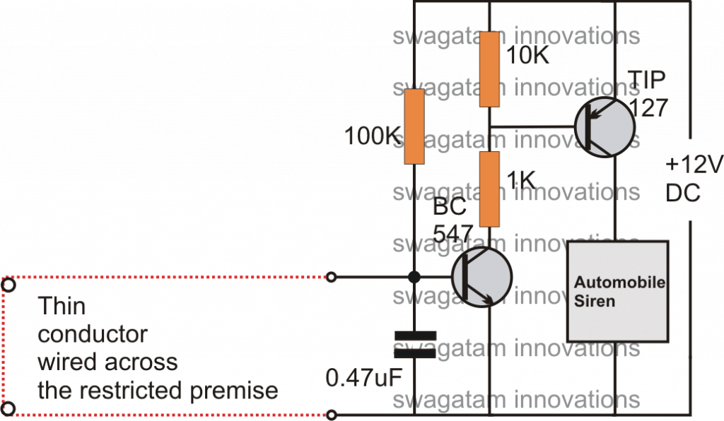
15022016 Circuit Design of Burglar Alarm System. This burglar alarm project is based on PIR sensor UM3561 and Speaker. Wire Break Sensor Alarm Circuit Schematic.
It is different from others burglar alarm systems because is a very simple diy project and can offer you great satisfaction. Circuit Diagram Of Intruder Alarm System 6 Conclusions Burglary Is Scientific. A wooden clothes peg.
PIR sensor used to detect body motion and UM3561. The R1 stand gives to get the maximum score. This circuit detects an unauthorized entry of any person in the houses or in any particular area.
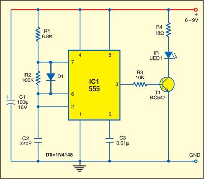
All you need is just to place this circuit in front of the locker or below the mat so when any unknown person come and walk over the switch the circuit will trigger and sound of alarm comes. The IR transmitter or IR LED is connected to a current limiting resistor of 150Ω and connected to supply. VADDESWARAM 522 502 April 2020 iPage LASER SECUIRTY ALARM SYSTEM DEPARTMENT OF ELECTRICAL AND ELECTRONIC ENGINEERING CERTIFICATE This is to certify that the project.
The Alarm Sound Super Bell loud forever until will cut power supply to go out. Alarm System Wiring For The Main Panel. We come to try build the circuit steal model to is simple better.
The project involves the use of Arduino motion sensor buzzer LCD display and a simple program. It is a simple and cost-effective solution for the security system. The units ability in communicating back to its monitoring system is truly a crucial aspect for determining the efficiency of the alarm.
The latch stage basically built around the CD4013B CMOS dual D-type flip-flop 1 7. For best Light source we can use Laser diode which will work for few km. The above circuit uses timer IC 555 to detect and sound alarm upon detecting intruders.
This will pick up the laser light and enable the alarm. They help alert security personnel especially in situations where no obvious break-in has occurred. Apart from being one of those fun science projects the aim is to make a simple burglar alarm using electronics and a clothes peg as a switch.
The main benefit of the circuit is that these can be implied in two places at a time as two different switches produces two different sounds. 08012020 In this tutorial we are going to design a burglar alarm circuit. The circuit illustrated here is used as Burglar alarm.
A 9V battery the correct scientific term is a cell A 9V battery cell holder. The attached schematic should demonstrate how. The sensor detect any motion in its permissible range and triggers the alarm.
Speaker to produce Police siren after any movement detection. The project uses a PIR motion sensor instead of a Transmitter and a receiver. Burglar alarm circuit for further processing.
Many types of motion sensors can sense motion in total darkness without an intruder becoming aware that an alarm has been triggered.

Wiring Material Motorcycle Alarm With Transistor Circuit Diagram Transistors Alarm Circuit Diagram

How To Make Burglar Alarm Circuit By Using Timer Ic 555 Electronic Projects Power Supply Circuits Circuit Diagram Symbols Audio Amplifier Circuit Pdf Engineering Projects
Pcb Layout Of Fire Alarm Circuit Pcb Circuits

Burglar Alarm System

5 Simple Alarm Circuits For Protecting Your Home Office From Theft Homemade Circuit Projects
Infrared Burglar Alarm Detailed Circuit Diagram Available

Simple Burglar Alarm Circuit Diagram Circuit Diagram Burglar Alarm Electronics Circuit
An Scr Based Burglar Alarm Circuit Diagram


How To Make A Burglar Alarm Circuit For Your Home Security Home Security Systems Wireless Home Security Systems Burglar Alarm


0 comments:
Post a Comment