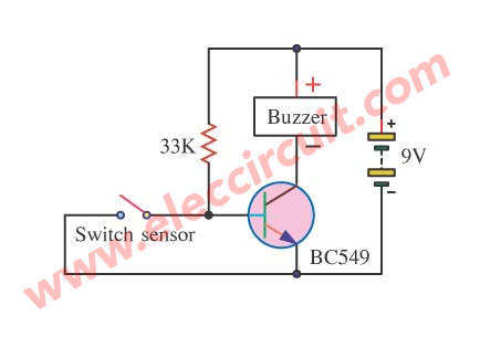
The circuit will make a noise to warn work as soon as detect which be switch model usual close the circuit or aluminum eliminated separate. Burglar alarms can be configured in two ways namely open-circuit and closed-circuit systems.

Photodiode Alarm Circuit
A control panel that acts as the brain of the system monitoring the alarm circuit an alarm box with a warning mechanism and sensors for transmitting signals to the control panel.

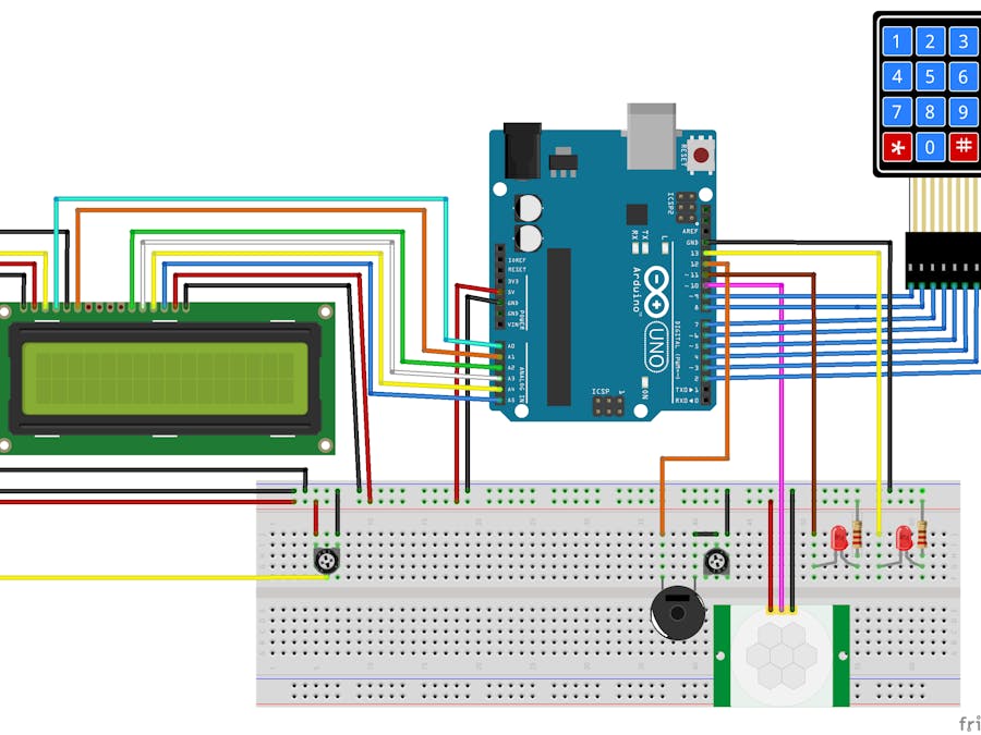
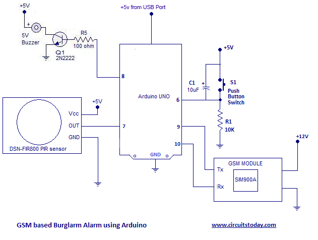
Mechanism of burglar alarm circuit. The first one is a simple burglar alarm circuit using pir sensor arduino a buzzer and a push button switch. This burglar alarm system circuit is using a infrared proximity detector that triggers an alarm when the rays falling on its sensor are interrupted. IC 555 is connected as comparator with pin 6 connected with positive supply the output goes high-1 when the trigger pin 2 is at lower than 13 level of the supply voltage conversely the output goes low-0 when it is above 13.
In this burglar security alarm circuit the cathode of the IR transmitter is connected to the positive supply while the anode to the ground supply through a resistor of 150 Ω. 08012020 Burglar Alarm Circuit Electronics Projects. 08082017 Burglar Alarm model the circuit closes This circuit works with battery 9V a piece is very small.
The PIR sensor is used to monitor a particular locationfield for. This circuit uses a popular timer IC which is 555. Used to detect any human activity or entry gate security violations.
For the work happens independently dont be under house electricity. It is placed at a suitable position from the IR receiver. So UM3561 activated and start producing sound with Speaker.
Burglar Alarm System Circuit. Direct incidence of radiation on the photodiode is applicable in burglar alarm circuit. 15102020 Most burglar alarms use a closed-circuit system.
27042020 An intrusion detection alarm or burglar alarm is an alarm circuit which is consisting of some electronics components. There are 2 categories of circuitsthe closed-circuit as well as the open-circuit system. 18032008 Burglar Alarm Circuit using Arduino and PIR Sensor with GSM Module for SMS Alert.
When the door is closed the switch is pulled shut and completes the circuit. It is placed at the maximum possible range from photo diode. When the electric current gets cut the alarm system automatically gets activated.
05042017 What is a Burglar Alarm System. In a closed circuit system when a door or window is shut the electric circuit is closed. A burglar alarm system consists of a series of electrical components that are connected to a property.
When the door is opened the circuit is broken triggering the alarm relay. The IR transmitter or IR LED is connected to a current limiting resistor of 150Ω and connected to supply. The application of electronics in this modern age is simply inexhaustible and this group form more interest in the alarm system after negotiating the increase in the case of burglaries in homes cars etc.
The selection of a proper alarm is not a simple matter because the need of each individual home owners or businessman is different like a set of finger prints. 12122015 This burglar alarm circuit is very simple whenever PIR sensor detects any human body movement its OUTPUT pin becomes HIGH which is connected to UM3561s Power supply PIN 5. IR LEDs has massive use in remote controls and safety alarm systems.
In this project we have designed 2 burglar alarm circuits using arduino and pir sensor. Now when any body will pass that door or place the wire will break and the transistor will get switch on and activate the device connected to it. It is different from others burglar alarm systems because is a very simple diy project and can offer you great satisfaction.
It is a simple and cost-effective solution for the security system. The alarm makes use of different types of sensory elements like motion sensor or laser security alarm for intrusion detection. The main components of a burglar alarm system are as follows.
This works by continuously running an electric current around a perimeter. As it constantly runs users are alerted in real-time whenever the circuit is broken or cut when an intruder opens a door or window. The project uses a PIR motion sensor instead of a Transmitter and.
They can set off by Door Sensors. This circuit detects an unauthorized entry of any person in the houses or in any particular area. The cathode of the photo diode is connected to supply while anode is connected to 10KΩ resistor.
In this tutorial we are going to design a burglar alarm circuit. 15022016 Circuit Design of Burglar Alarm System. This means that electricity can flow from one end to another in the.
Today you can discern different kinds of alarms with different working principles developed over the years. 08062018 Burglar alarm circuits are triggered in a variety of ways. The IR LED is fit on one side of the door frame and the photodiode on the other.
Other end of the resistor is connected to ground. A burglar alarm takes care of the internal security of your house. These have magnetic switches embedded in the door frame that align with a magnet in the door.
If an intruder breaks in a house through a door or window his movements will be detected by a switch which will trigger the burglar alarm. The two points of wire connections shown in both the circuits to connect a very thin copper wire from one end to another at the door or at any other place that you want to secure. Via sensors and contacts they detect movement or the opening of doors and windows upon which a loud alarm is produced to alert those nearby of the unauthorised entry.
Picture of our Burglar Alarm project. The burglar alarms also known as security alarms or Home security systems are deliberately contrived to guard your house against break-ins.
Arduino Alarm System Arduino Project Hub
Burglar Alarm Circuit And Projects Diy

How Do Burglar Alarms Work And How Do They Protect You From Crime

Simple Burglar Alarm Circuit Diagram Circuit Diagram Burglar Alarm Electronics Circuit

How To Make A Burglar Alarm Circuit For Your Home Security Home Security Systems Wireless Home Security Systems Burglar Alarm

9 Burglar Alarm Circuit Ideas Electronics Projects Circuits
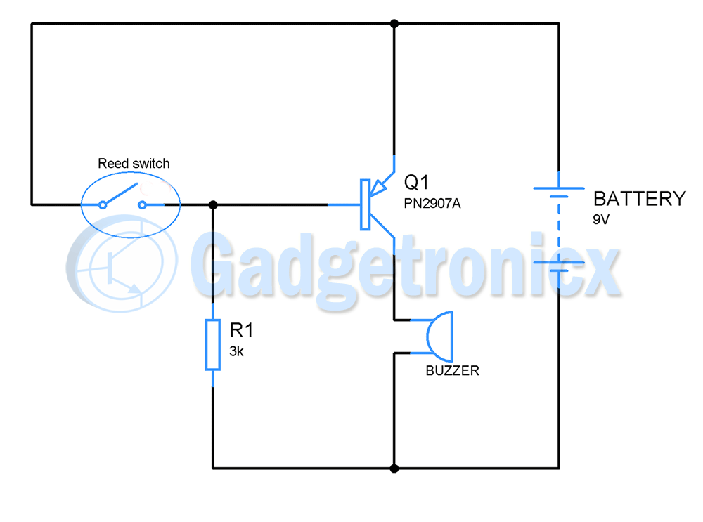
Thief Door Alarm Using A Transistor Gadgetronicx
9 Burglar Alarm Circuit Ideas Electronics Projects Circuits
Long Range Cordless Burglar Alarm Circuit And Its Working


0 comments:
Post a Comment