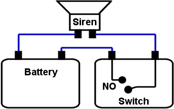
Speaker is connected to any terminal of the battery and one side of the house with metal wire. We come to try build the circuit steal model to is simple better.

Simple Security Alarm Circuit Working And Applications
This same design is commonly used for.

Examples of burglar alarm circuit. Project of a simple wire break or burglar alarm using 555 IC. 15022016 Circuit Design of Burglar Alarm System. 18032008 In this project we have designed 2 burglar alarm circuits using arduino and pir sensor.
Picture of our Burglar Alarm project This circuit uses a popular timer IC which is 555. Simple burglar alarm circuits. These have magnetic switches embedded in the door frame that align with a magnet in the door.
So UM3561 activated and start producing sound with Speaker. 12122015 Circuit Diagram and Explanation. 10122017 Example Dsc Security System Burglar Alarm.
IC 555 is connected as comparator with pin 6 connected with positive supply the output goes high-1 when the trigger pin 2 is at lower than 13 level of the supply voltage conversely the output goes low-0 when it is above 13. It is placed at the maximum possible range from photo diode. While a switch is opening up S2 S3 S4 or shutting S5 S6 S7 either SCR1 or SCR2 activates.
We should pay more attention to our security here burglar alarm designed to detect. The PIR sensor is used to monitor a particular locationfield for any movementmotion. They can set off by Door Sensors.
BZ1 is a powerful alarm with the continuous sounding sort. The burglar deterrent circuit is constructed using two monostables. This burglar alarm circuit is very simple whenever PIR sensor detects any human body movement its OUTPUT pin becomes HIGH which is connected to UM3561s Power supply PIN 5.
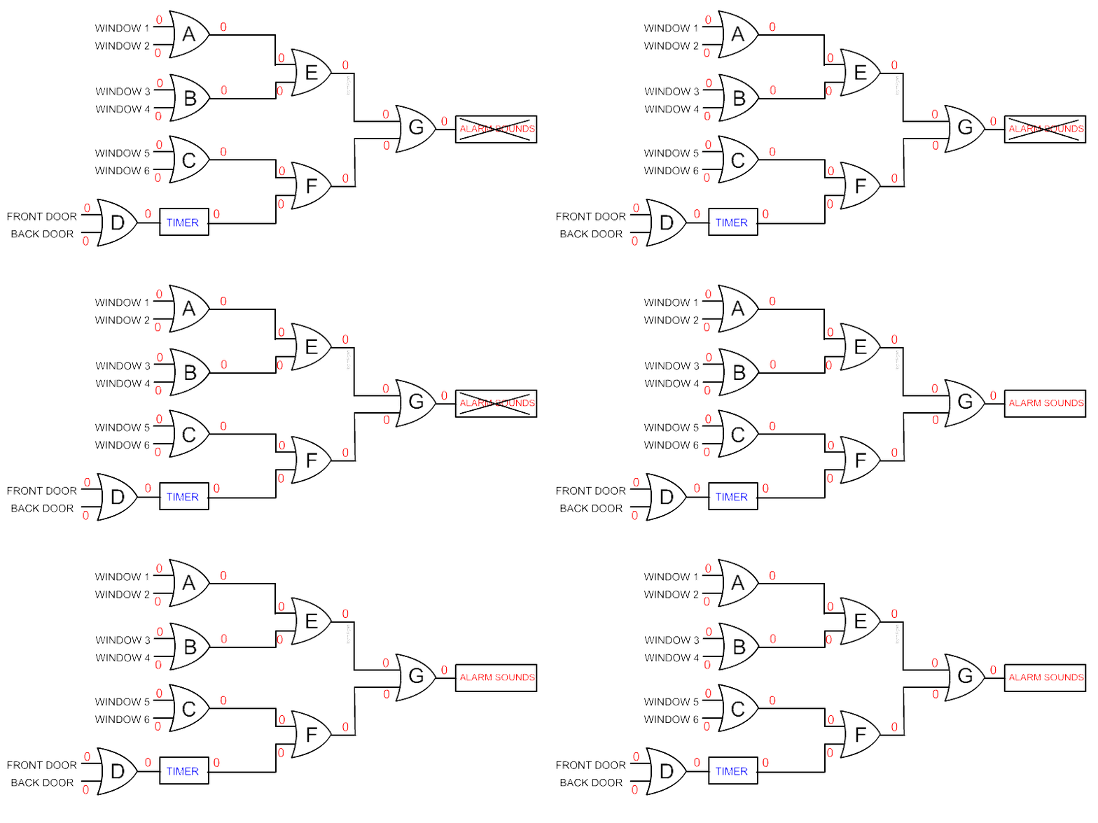
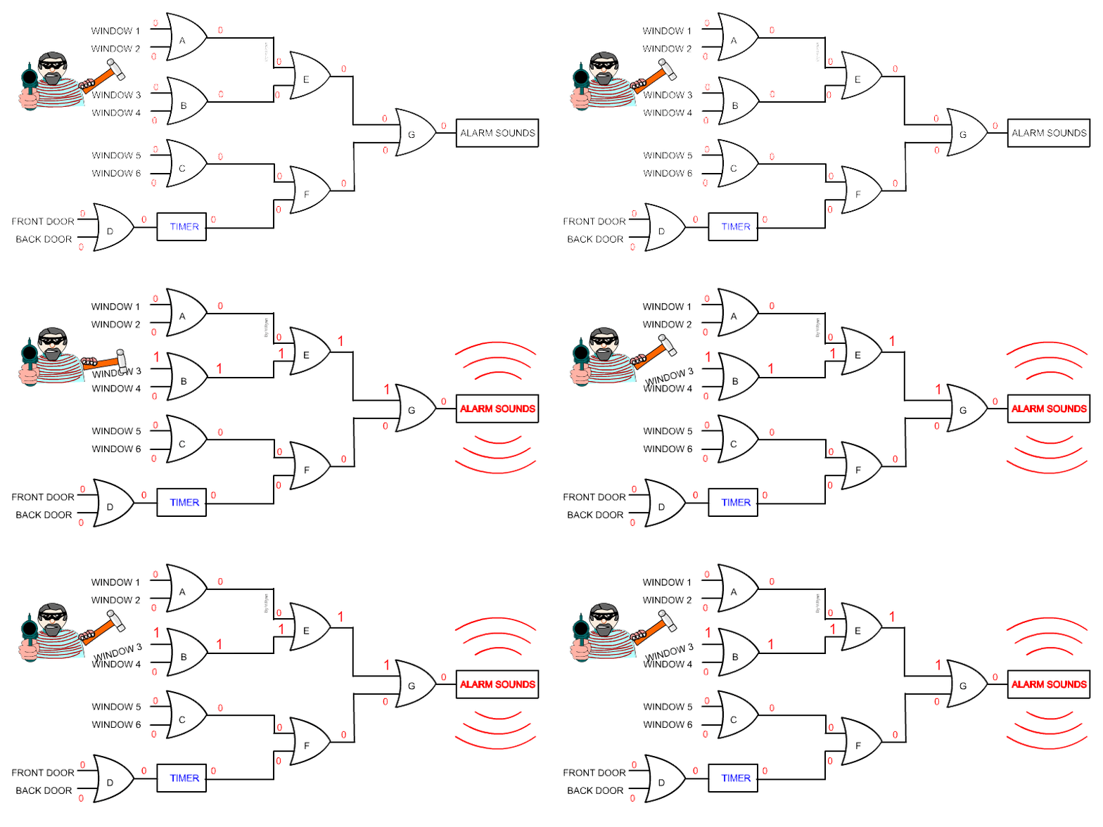
The circuit can be used for variety of other purposes when a wire break switch or alarm is required. CHAPTER TWO LITERATURE REVIEW 21 SENSORSMOTION SENSORS Motion sensors are types of electronic security device that senses movement and usually triggers an alarm. LITERATURE REVIEW OF A BURGLAR ALARM SYSTEM.
28062020 The circuit here is a good example. Visual display of the burglar alarm circuit. Used to detect any human activity or entry gate security violations.
Burglar Alarm Working Explained When the door is closed the photiode will be facing the black surface and no IR rays will be reaching the photodiode and hence the output of the ir sensor will be Zero. In this circuit you can connect any alarm device with operating current rating of 10mA to 10A. Circuit Diagram Of Intruder Alarm System 6 Conclusions Burglary Is Scientific.
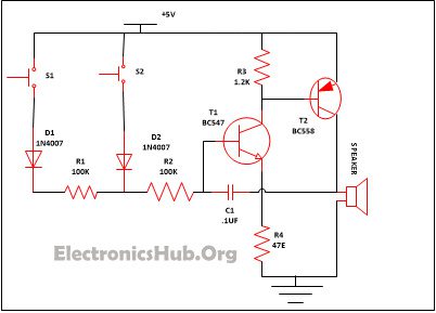
The circuit is very simple and using not more three parts which are a 555 timer IC a 100K resistor and a buzzer or relay. It is placed at a suitable position from the IR receiver. 12072020 High Power Alarm Driver Circuit.
This triggers SCR3 through D1 D2 and R5. Burglar Alarm System Circuit. When the door is closed the switch is pulled shut and completes the circuit.
Burglar Alarm Wiring For Securing Doors. This burglar alarm system circuit is using a infrared proximity detector that triggers an alarm when the rays falling on its sensor are interrupted. Anti Theft Car Alarm Circuit.
It is different from others burglar alarm systems because is a very simple diy project and can offer you great satisfaction. The cathode of the photo diode is connected to supply while anode is connected to 10KΩ resistor. This circuit can be used with power supply from 5V to 15V depending on relay sure enough.
The working of PIR Burglar alarm is very simple. The home alarm circuit is designed to build up a circuit that goes through the paper house as shown in the figure 1. The alarm makes use of different types of sensory elements like motion sensor or laser security alarm for intrusion detection.
When the door is opened the circuit is broken triggering the alarm relay. The IR transmitter or IR LED is connected to a current limiting resistor of 150Ω and connected to supply. Aluminum foil speaker battery Figure 1.
27042020 An intrusion detection alarm or burglar alarm is an alarm circuit which is consisting of some electronics components. The first one is a simple burglar alarm circuit using pir sensor arduino a buzzer and a push button switch. In this burglar security alarm circuit the cathode of the IR transmitter is connected to the positive supply while the anode to the ground supply through a resistor of 150 Ω.
08062018 Burglar alarm circuits are triggered in a variety of ways. At this period the economy not good Make have steal plentiful. Other end of the resistor is connected to ground.
9 Burglar Alarm Circuit Ideas Electronics Projects Circuits. PIR Burglar Alarm Circuit. The circuit in figure 2 is using a 12V relay at the output.
The ringing of the bell activates several monostables and after an appropriate delay turns on a suitable alarm or a pre-recorded programmed sound. Many types of motion sensors can sense motion in total darkness without an intruder becoming aware that an alarm has been triggered. In such a circuit a less powered SCR is employed to activate.
When the door is opened the photodiode will be facing the IR LED and the IR rays will be directly hitting the photodiode. It works as when any infrared heat source comes under the range of pir sensor it processes it give output of power supply and this ouput is fed at the base of the BC548 transistor which act as a switch and it switches on the circuit and the buzzer goes on and we detect the burglarintruder. At the output of the circuit you can connect any type of 12V and 200 to 300mA current rating buzzer siren horn alarm etc.
PIR sensor Passive Infrared sensor widely used in motion detection applications and security based applications the following project is a burglar alarm circuit by using PIR sensor and three siren sound generator IC UM3561. 08082017 The C1 C4 to protects a noise signal from either switch which may cause the alarm to be up. This can be whatever you want like the bark of a dog or even a voice saying something appropriate.
A greater powered SCR.

Simple Burglar Alarm Circuit Diagram Circuit Diagram Burglar Alarm Electronics Circuit

Pdf Development Of A Simple Sound Activated Burglar Alarm System

Unique Fire Alarm System Control Module Wiring Diagram Diagram Diagramtemplate Diagramsample

Security Electronics Systems And Circuits Part 7 Nuts Volts Magazine

Wiring Material Motorcycle Alarm With Transistor Circuit Diagram Transistors Alarm Circuit Diagram

5 Simple Burglar Alarm Circuits For Protecting Your Home Office From Theft Homemade Circuit Projects Electronic Circuit Projects Circuit Projects Circuit

Tamper Proof Security System Wiring


0 comments:
Post a Comment